
Device guide
GPS K18: understanding RF, lens reflections and magnetic fields
Explore the three phenomena associated with the K18 and build a bench comparison using known references, recorded observations and careful interpretation.
What this instrument helps you study
An instrument beeps near an object. What can you conclude? First, that something made the instrument respond. Identifying the phenomenon, locating its source and establishing the object’s function are subsequent steps. Learning begins by separating those questions.
We will use the GPS K18 to explore three functions: RF, lens inspection and magnetism. GPS is the identified brand of this instrument; the name does not establish a satellite positioning function. The manual and exact unit revision have not yet been confirmed. Until those details are available, we will work with physical principles and comparisons you can record, without treating unverified frequency ranges, reach, accuracy or commands as established device specifications.
Academic research has studied a detector called K18, but the name does not establish that the investigated device has the same revision or brand as the laboratory unit. That research helps explain optical observation and its limitations.[1]
Three modes, three physical questions
RF: is radio energy being received?
Radio waves belong to the electromagnetic spectrum. Frequency describes how many oscillations occur each second; wavelength describes a spatial distance. Detecting energy in this part of the spectrum differs from recovering the information carried by a communication.[2]
On a simple RF detector, an indication can help compare conditions, but an alarm or an uncalibrated bar does not automatically give a power measurement. It also does not reveal the sender, the communication’s contents or its purpose. To begin, we will answer a clearly defined question: does the response change when you change the state of a known source you own?
Optics: where does the reflection come from?
In some lens-and-sensor arrangements, light returns toward its source: retroreflection. Optical detectors combine illumination and observation to look for this return. Angle, distance and reflections from other objects complicate interpretation. The LAPD study describes these mechanisms and false positives; its findings do not certify the GPS K18.[1]
A switched-off camera still has an optical assembly. Finding a reflection, however, does not establish recording, transmission or storage. Confirmation requires identifying the object. Comparing a known camera with a shiny screw helps teach this distinction without searching for an unknown device.
Magnetism: does the response follow a field?
Magnetic sensors respond to fields, not to an object’s product category. One example is the Hall effect: a magnetic field can produce a transverse voltage in a powered sensing element. Field orientation and sensor construction influence the response. Some circuits provide a continuous output; others only change state when a threshold is crossed.[3]
The sensor inside this K18 has not been identified. The Hall effect explains a possible technology without claiming that it is installed. A known magnet helps study repeatability of the reported function; a response does not make the instrument a universal metal or tracker detector.
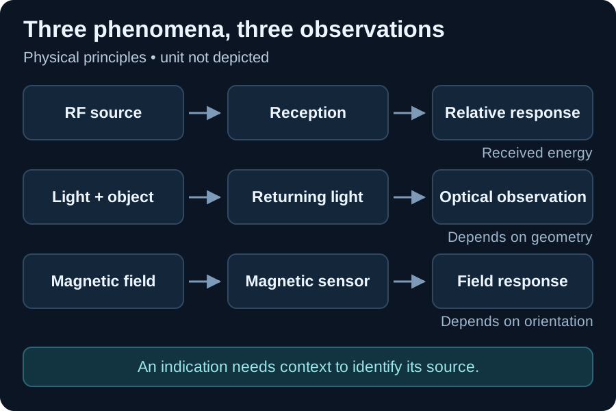
Teaching diagram of the three phenomena. It does not reproduce the internal construction or appearance of the GPS K18 unit.
Identify the unit before operating it
Prepare a record with readable photographs of the label, front, connectors and accessories. Copy the complete model name and keep the matching manual. This prevents specifications from unrelated products sharing the K18 name from entering your record.
| Record this information | Why it changes the exercise |
|---|---|
| Identification and revision | Determines which manual applies |
| Each button and accessory’s function | Prevents confusion between modes and connections |
| Power supply and battery indication | Helps reproduce the same condition |
| Documented ranges and limits | Establishes which reference sources are meaningful |
| Meaning of the indication | Separates an alarm, a relative scale and a measurement |
Use only functions confirmed in your unit’s manual. RF, optics and magnetism below are exercise categories, not a universal button sequence. If a control remains unidentified, record that gap instead of experimenting with connections.
Laboratory: learn a reference before interpreting an alert
Objective: produce repeatable comparisons of one phenomenon at a time. Prepare an owned RF source whose frequency falls within documented coverage, an owned camera with a visible lens, a shiny object without a camera and a small reference magnet. A ruler, marks on the table and a recording sheet complete the setup. Follow each object’s instructions; avoid strong magnets and improvised intense illumination.
-
Define the question. Write, for example: “Does the RF indication change when I turn this source on?” Choose one condition per trial. Do not change the source, distance and setting simultaneously.
-
Mark the positions. Assign a location to the detector and another to the object. Record approximate distance, orientation and lighting. Photograph the setup without people or private information in the frame.
-
Record the background. Observe the selected mode without the reference active or present. Record the actual available indication: sound, light or number. Do not convert “two bars” into a unit the manual does not define.
-
Compare the RF source. Alternate source off, on and off again while preserving positions. Allow enough time for each observation and repeat three cycles. If the response is inconsistent, the exercise is inconclusive; check coverage and configuration before interpreting it.
-
Compare the optical objects. Observe the known camera and the shiny object under the same lighting. Then change only the viewing angle. Describe where the reflection appears and how it changes without classifying every bright spot as a lens.
-
Compare the magnet. In the documented mode, bring the reference closer and move it away without touching the sensor or forcing accessories. Repeat the same path. In a separate series, change only orientation. Record whether the indication returns to background when the object moves away.
-
Change the observer. Ask another person to describe the same indications using your record. Disagreements help reveal vague wording, poorly defined positions or changing conditions.
Example record and interpretation
Use these ILLUSTRATIVE results to learn how to fill in your record. They are fictional examples, with no GPS K18 measurements, and do not represent its actual sensitivity or performance.
| Proposed trial | Illustrative observation | Supported interpretation |
|---|---|---|
| Owned source off / on / off | Background / increased indication / background | The response followed that change in this example |
| Known camera, two angles | Visible reflection / faint reflection | Geometry changed the observation |
| Shiny object without a camera | Visible reflection | Brightness alone does not classify the object |
| Magnet near / far | Alert / no alert | The indication followed that reference |
| RF source on, no change | Same background | Detection was not demonstrated under that condition |
The last outcome matters as much as the first. It can justify reviewing the setup, but it does not establish that the source stopped transmitting. Similarly, responding to a known object demonstrates a particular comparison, not an ability to find every similar object.
Common mistakes and the next step
Increasing sensitivity until everything triggers removes the comparison’s usefulness. Changing several settings together prevents attributing the difference to a cause. Recording only “suspicious” mixes observation with interpretation. Prefer “the indication increased when the reference was switched on, over three cycles, with position unchanged”.
Finish with one page containing identification, configuration, setup, observations and unresolved questions. Keep the record so you can compare conditions when you repeat the exercise and explain how you reached your conclusion. To study frequency and amplitude separately, continue with the tinySA Ultra guide. To compare announcements from known networks, explore the Marauder Wi-Fi inventory.
References
-
Sami, S.; Tan, S. R. X.; Sun, B.; Han, J. LAPD: Hidden Spy Camera Detection using Smartphone Time-of-Flight Sensors. ACM SenSys, 2021. Sections 2.2–2.3: retroreflection and optical detectors. Source. Accessed 17 October 2026. ↩ ↩2
-
NASA. Radio Waves. Tour of the Electromagnetic Spectrum. Supports radio waves, frequency and applications; does not specify the K18. Source. Accessed 17 October 2026. ↩
-
Allegro MicroSystems. Hall-Effect Sensors Applications Guide. “What is Hall-effect?” and “Operation”: physical principle and field orientation. Source. Accessed 17 October 2026. ↩